BH eStore: Your One-stop Marine & Offshore Electrical Supplier
Currency
- Flame Retardant, BLACK (IEC 60332-3-22 Category A)


- Fire Resistant, ORANGE (IEC 60331-21)

- Conductor (IEC 60228) - Class 2
- Flame Retardant, GREY (IEC 60332-3-22 Category A)


- Fire Resistant, ORANGE (IEC 60331-21)


0.6/1KV [Cores type]
- Flame Retardant, BLACK RFOU P1/P8, Mud Resistant (IEC 60332-1, 60332-3-22)

- Fire Resistant, BLACK BFOU P5/P12, Mud Resistant (IEC 60331-21, IEC 61034, IEC 60754-1, IEC 60754-2)
250V [Pairs, Triads, Quads]
- Flame Retardant, GREY RFOU (IEC 60332-1, 60332-3-22)
• Armoured, Collective Screen, RFOU (C) S2/S6, Mud Resistant (IEC 60092-350, IEC 60092-351, IEC 60092-376)

• Armoured, Individual Screen, RFOU (i) S1/S5, Mud Resistant (IEC 60092-350, IEC 60092-351, IEC 60092-376)

• Armoured, Individual/Overall Screen, RFOU (I/C), Mud Resistant (IEC 60092-350, IEC 60092-351, IEC 60092-376)

- Fire Resistant, GREY BFOU (IEC 60331)
• Armoured, Collective Screen, BFOU (C) S4/S8, Mud Resistant (IEC 60092-350, IEC 60092-376)
• Armoured, Individual Screen, BFOU (i) S3/S7, Mud Resistant (IEC 60092-350, IEC 60092-376)
• Armoured, Individual/Overall Screen, BFOU (I/C), Mud Resistant (IEC 60092-350, IEC 60092-376)
Cables for use in hazardous area are not specifically Ex certified, but are required to be constructed from materials as specified in IEC60079-14 and manufactured to relevant standards so that failure is unlikely, providing that the cable has been correctly installed. Typical standards for manufacture of cables for marine and offshore platforms are BS683 and IEC60092.
Cables are selected for fire resistance and/or flame retardant properties, and two standards are relevant:
A cable manufactured in compliance with this standard will continue to operate in a fire without disruption of essential circuits and emergency circuits. Fire resistance is necessary in cabling for essential safety circuits that are required to operate in a fire for a specified time. These cables are usually use at emergency controls, fire alarm systems, PA Systems, CO2 systems, emergency DC systems & radio communication systems.
A cable manufactured in compliance with this standard is self-extinguishing and will not propagate the fire. The important factors in the performance of cables in a fire include fire survival, fire retardancy, fire propagation, toxicity and smoke emission.
Cables may be manufactured from materials (typically polymer compounds) that produce low smoke & fume emissions during a fire. Cables with this capability are known as low smoke & fume (LSF), low smoke zero halogen (LSZH), or zero halogen low smoke (ZHLS).
IEC60079-14 specifies the cable requirements for fixed equipment in Zone 1 & 2. Cables sheathed with thermoplastic, thermosetting or elastomeric (“rubber-link”) material may be used in fixed wiring installations. Generally, they should be circular and effectively filled, with extruded bedding. Any filler must be non-hygroscopic. Mineral insulated metal sheathed cable is suitable for use in hazardous areas.
Cables are normally armoured, but non-armoured types may be used if mechanically protected. Cables commonly used in the offshore industry are EPR/CSP with braided wire armour, although XLPE/LSF single wire armoured (SWA)type may be found on fixed platforms.PVCor XLPE/SWA/PVC is often used in land installations.
Copper conductors may be used for all sizes of cable, but Aluminum conductors must have a cross-sectional area not less than 16mm², and be connected via suitable terminals.
Examples of the various permitted cable insulation types are given in the table below.
| ElastomericElastomeric | Chlorosulphonated polyethylene | CSP |
| Cross-linked polyethylene | XLPE | |
| Ethylene propylene rubber | EPR | |
| Ethylene vinyl acetate | EVA | |
| Natural rubber | NR | |
| Polychloroprene | PCP | |
| Silicone rubber | SR | |
| Thermoplastic | Polyethylene | PE |
| Polypropylene | PP | |
| Polyvinyl chloride | PVC |
Portable and transportable electrical equipment may be wired using cables having a heavy polychloroprene or alternative equivalent synthetic elastomeric sheath, or a heavy tough rubber sheath, or manufactured from materials providing equally robust construction. The minimum cross-sectional area for such cables is 1.0mm².
Portable electrical equipment that does not exceed 250V to earth and 6A and is not subject to heavy mechanical stress may have an ordinary polychloroprene or tough rubber sheath, or be of equivalent construction.
These would usually be screened cables connected to intrinsically safe ‘ia’ equipment and must withstand a 500Vac or 750Vdc test between conductor to earth, conductor to screen and screen to earth. Minimum conductor or conductor strand size is 0.1mm².
The internationally agreed L.V. colour code is now:
Cables, particularly offshore types, may be encountered with other colour codes.

References: Assets Training & Technical Services Pte Ltd Copyright © March 2015
Specimens
A specimen of the completed cable 1,200mm long shall have 100mm of sheath or outer coverings removed from each end.
Test Conditions
(1) The specimen shall be held horizontally by means of suitable clamps at each end of the sheath or protected portion.
(2) The transformer shall be connected to the specimen through a 3A fuse in each phase and a 5A fuse shall be inserted in the neutral circuit which shall be earthed.
(3) Adjacent conductors shall be connected to the different phases.
Ignition Source
(1) The source of ignition shall be a 610mm long tube type burner which produces a line of closely spaced flames.
(2) The flame temperature shall maintain 750°C during the test.
Test Procedure
(1) The electrical supply shall be switched on and the voltage adjusted to that of the rated voltage of the specimen and this shall be applied continuously during the test.
(2) The gas flame and test voltage shall be applied continuously for a period of 3 hours
(3) Not less than 12 hours after flame has been extinguished, the specimen shall again be energized as describe above.
Requirement No failure of any of the 3A fuses occurs when the withstand voltage is applied exceeding the rated voltage.
*Note - Fire Test shall be according to, IEC 60331-1 (D >20mm²), IEC 60331-2 (D ≤20mm²): 830°C
or
IEC 60331-21: 750°C (D is the overall diameter of the cable)
Specimens
A specimen shall be a piece of the finished wire or cable 600±25mm long.
Test Conditions
(1) The specimen shall be kept at a temperature of 23±5°C for minimum 16 hours at a relative humidity of 50±20% before testing
(2) The specimen shall be fixed at two positions and aligned vertically within a 3-side metallic screen 1,200±25mm high, 300±25mm wide and 450±25mm deep with open front and closed top and bottom.
(3) Distance between the top clamp and the bottom clamp is 550±25mm.
(4) Distance between the bottom of specimen and the base of the screen is approximately 50mm.
Ignition Source
(1) When propane gas is used, the bunsen burner shall be adjusted to give a flame approximately 175mm long with an inner blue cone approximately 55mm long.
(2) When natural gas is used, the bunsen burner shall be adjusted to give a flame approximately 125mm long with an inner blue cone approximately 40mm long.
Test Procedure
(1) The axis angle between the burner tube and the specimen is45°
(2)The continuous period of time corresponding to the diameter as following table.
|
Overall diameter of test specimen |
Time for flame application |
|
(mm) |
(second) |
|
0.D≤25 |
60 |
|
25<0.D≤50 |
120 |
|
50<0.D≤75 |
240 |
|
0.D>75 |
480 |
Requirement
After all burning has ceased, the surface of the specimen shall be wiped clean and
(1) the charred or affected portion shall not have reached within 50mm of the lower edge of the top clamp, and
(2) maximum length of downward charred surface shall not exceed 540mm from the lower edge of the top clamp.

Specimens, Category & Designation
The specimens shall be a number of finished wire or cable in minimum 3,500mm long, and the total number of 3.5m test pieces in the test sample should be in accordance with one of the three categories as follows.

Test Conditions
(1) The vertical test chamber shall have a width of 1.0m, a depth of 2.0m and a height of 4.0m, and the floor of the chamber should be raised above ground level, and air being admitted at the base of the test chamber through an aperture of 800mm x 400mm situated 150mm from the front wall of the test chamber.
(2) The ladder shall have a height of 3.5m, 9 rungs, and two types such as standard ladder of 500mm width and wide ladder of 800mm width.
Ignition Source
(1) The ignition source shall be of ribbon-type propane gas burner, flow meters, venture mixer and whose flame-producing surface consist of a flat metal 341mm long, 30mm wide.
(2) The air input rate should be 76.7 l/min, and the propane flow rate should be 13.3/min at one atmosphere and 20°C to provide a nominal 73.7 x 10⁶ J/h (70,000 Btu./h) to each burner.
(3) The burner shall be arranged horizontally at a distance 75mm from the front surface of the specimen and 600mm above the floor of the test chamber.
(4) The point of application of the burner flame shall lie in the center between two cross-bars on the ladder and at least 500mm above the lower end of the specimen.
Test Procedure
(1) Determine the total volume per meter of non-metallic of one test piece and the number of specimens to be mounted.
(2) After mounted, the flame shall be applied for a period of specified flame application times.
Requirement
After burning has ceased, the charred portion shall not have reached a height exceeding 2.5m above the bottom edge of the burner, neither at the front nor the rear of ladder.

Specimens
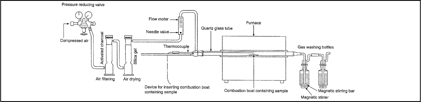
The specimen shall be compound for insulation and jacket in weight of 500mg to 1000mg.
Test Conditions
(1) The combustion boat (L:76mm, W:15mm, D:10mm) with the specimen shall be placed in the combustion tube (L:700mm, Inside dia.:40mm).
(2) The combustion tube shall be placed in the tube furnace with thermocouple.
(3) Two wash bottles containing at least 200ml of 0.1M sodium hydroxide shall be connected to the combustion tube.
Test Procedure
(1) The temperature of tube furnace shall be maintained at 800±10°C for 20 minutes.
(2) The combustion gas shall be filtered through the sintered glass crucible and titrating 0.1M.
Determination of Halogen Acid Content The amount of halogen acid, expressed as milligrams of hydrochloric acid per gram, is;
DOWNLOAD: HALOGEN ACID CONTENT

where, A : Volume of 0.1M ammonium thiocyanate solution used in the test.
B : Volume of 0.1M ammonium thiocyanate solution used in the blanktest.
m : Mass of sample taken (grams)
M : Molarity of ammonium thiocyanate solution


Specimens
The specimen shall be of compound for insulation and jacket in weight of 1000±5mg.
Test Conditions
(1) The combustion boat (L:76mm, W:15mm, D:10mm) with the specimen shall be placed in the combustion tube (L:700mm, Inside dia.:40mm).
(2) The combustion tube shall be placed in the tube furnace with thermocouple.
(3) Two wash bottles containing at least 220ml of 0.1M sodium hydroxide shall be connected to the combustion tube.
Test Procedure
(1) The temperature at the position of the boat shall be not less than 935°C and the temperature at position 300mm from the boat in direction of the air flow shall be not less than 900°C for 30minutes.
(2) The air flow shall be adjusted by means of needle valve at 0.0155xD² l /h±10% (D: tube inner dia. in mm) and is kept constant during the test.
(3) The pH value and conductivity shall be determined at the end of the test.
DOWNLOADS: HALOGEN ACID CONTENT
Determination of pH value and conductivity
The weighted value of pH and conductivity are calculated as follows;

where, x is the pH value of each non-metallic material i.
c is conductivity of each non-metallic material i.
w is the weight of each metallic material i per unit length of cable.
Requirements
(1) The weighted pH value should not be less than 4.3, when related 1l of water.
(2) The weighted value of conductivity should not exceed 10µs/mm.
Specimens
The specimen shall be compound taken from cable in length of 70-150mm, width of 6.5±0.5mm, thickness 3.0±0.5 mm.
Test Conditions
(1) The column shall be of a heat resistant glass tube (H:450mm, Inside dia.:75mm ) having the supplier of oxygen and nitrogen with flow measurement and control devices.
(2) The specimen holder shall hold the specimen vertically in the center of the test column.
Ignition Source
(1) The igniter shall be a tube with a small orifice ( 1~3mm in diameter) having a gas flame.
Test Procedure
(1) The oxygen gas shall flow in the column at the rate of 4±1cm/sec. at 0°C temperature and pressure 101.3kpa until the suitable concentration of it. (2) The specimen shall be ignited and if it burns for at least 3 minutes or length of flame is more than 50mm, the concentration of oxygen shall be reduced. (3) The concentration of oxygen when the burning is extinguished shall be checked.
Calculation of Result
The Oxygen Index (O.I) shall be obtained by the formula;

where, O2 : Volumetric flow of oxygen, cm³/s
N2 : Volumetric flow of nitrogen, cm³/s


Specimens
The specimen shall be the sheet of 3 inch by 3 inch (76.2mm x 76.2mm) or a number of insulation in length of 3 inch.
Test Conditions
(1) The Test apparatus shall consist of test chamber, radiant heat furnace, specimen holder, photometric system and recorder.
(2) The furnace control system shall maintain the required irradiance level, under steady-state conditions with the chamber door closed, of 2.50±0.05W/cm² for 20 minutes
(3) The test specimens are exposed to the two test conditions within a closed chamber as follows;
A) Non-flaming condition: An electrically heated radiant- energy source mount.
B) Flaming condition: A six-tube burner flame in addition to the specified irradiance level from the heating element constitutes the flame combustion exposure.
Test Procedure
(1) The specimen shall be attached to the specimen holder and placed in the test chamber.
(2) The photometric system and recorder shall be started and at that time ignite the radiant heat furnace.
(3) After exposure of 20 minutes or until minimum light transmittance level have been reached over exposure of 20 minutes , the radiant heat furnace shall be extinguished and the gas in the chamber shall be exhausted until maximum transmittance is reached.
Calculation of Result
Calculate the maximum specific optical density (Dm) with a light transmittance corresponding to the minimum level reached during the test as follows;

where, V : Volume of the closed chamber, ft³(or m³)
A : Exposed area of the specimen, ft²(or m²)
L : Length of the light path through the smoke, ft (or m)
T : Percent light transmittance as read from the light-sensing instrument.

Measurement of smoke density of Cables burning under define conditions
Specimens
(1) The specimen shall consist of one or more samples of cable 1.00±0.05m long which shall be carefully straightened and then conditioned for at least 16 hours at 23±5°C
(2) The selection of number of test pieces shall be as following table;

(3) The test pieces shall remain in situ during the test as follows;
- cables shall be bound together at the ends, and at 300mm from each end, at which place they shall be clamped to the support by means of wire binders.
- bundles shall be tensioned at one or both ends by means of an appropriate device, e.g. a spring or weight
Note - It is recommended that small cables and flexible cables should be tensioned
Test Apparatus
(1) Test enclosure; a cubic enclosure with inside dimensions of 3,000±30mm and one side shall have a door with a glass inspection window.
(2) Photometric system; the light source and the receiver shall be placed externally in the center of both windows in the two opposite walls of the cube without making physical contact.
(3) Standard fire source; 1.00±0.01l of alcohol having no effect on the smoke emission of any cable under test.
Test Procedure
(1) Before each test, clean the windows of the photometric system to regain 100% light transmission after stabilization of the voltage.
(2) The test samples supported above the tray, start the air circulation and ignite the alcohol and that the door is closed.
(3) The test is considered as ended when there is no decrease in light transmittance for 5 minutes after the fire source has extinguished or when the test duration reaches 40 minutes.
Requirement
The minimum light transmittance shall be not less than 60%

Reference: Copyright © Seoul Electric Wire Co., Ltd