BH eStore: Your One-stop Marine & Offshore Electrical Supplier
Currency
Cable glands are used when terminating cables into electrical equipment. They must be selected according to the methods of explosion protection employed and the environmental conditions.
The requirements for cable glands include:
Ex d glands use with MICC (Mineral Insulated Copper Cable) or MIMS (Mineral Insulated Metal Sheath) cable in hazardous areas will be marked as ‘Ex d’.
Ex e glands may be use as a means of entry to Increased Safety Equipment providing they are fitted with an alternative ‘Ex e’ seal having increased clearance and creepage distances.
Two standards specify the constructional requirements for industrial cable glands, BS EN50262 and BS6121. References are used in the standards to identify gland function:
| Standard | Ref | Meaning |
| EN50262 | A | Outer seal only |
| EN50262 | B | Armour lock only |
| EN50262 | C | Outer seal & armour lock |
| EN50262 | D | Inner seal & armour lock |
| EN50262 | E | Inner seal, outer seal & armour lock |
| EN50262 | BARR | Inner barrier seal, outer seal & armour lock |
| BS6121 | W | Single wire armour |
| BS6121 | X | Braided wire armour |
| BS6121 | Y | Aluminum wire armour |
| BS6121 | Z | Tape Armour |
Cable gland may be marked with these references or with manufacturers’ type numbers:
Before 2006, there were no constructional standards giving the specific requirements for cable glands use in explosive atmospheres. IEC 60079-0:2006 gave the essential general requirements for hazardous area glands and details of the type tests to be included in the certification process. In 2011, edition had updated some of these test specifications. Since the issue of IEC 60079-14:2007, Ex glands must be certified as meeting the requirements of 60079-0.
Glands will be marked in accordance with IEC standards and ATEX directives, and display the corresponding certificate numbers.
It is normally a condition of safe use (‘X’ suffix on certificate) for glands for use on braided armoured cable that the gland shall only be used for fixed equipment and the cable must be effectively clamped (preferably within 300mm from the gland) to prevent pulling and twisting.
The correct selection of cable glands is very important. Factors to be considered include:
An additional consideration is electrolytic action caused by contact between dissimilar metals – this can result in increased corrosion and degradation of glands and cable entries.
Flameproof (Ex d) equipment introduces other considerations into the selection of glands:
| According to IEC60079-15:2007 | According to IEC60079-15:2013 |
| Is the enclosure direct or indirect entry? | Is the enclosure direct or indirect entry? |
| Does the enclosure contain a source of ignition? | Is the cable is less than 3m in length |
| Gas group of the equipment (IIA, IIB, IIC) | |
| Zone in which Equipment is installed | |
| Internal volume of the enclosure |
If the enclosure is indirect entry with an Ex e terminal chamber, then the glands can be single certified Ex e or Ex d/Ex e dual certified types.
If the enclosure is indirect entry with an Ex d terminal chamber, then the glands can be certified EX d, or Ex d/Ex e dual certified types. Ex d barrier type would be over-specified.
If the Ex d enclosure is direct entry, then the cable glands must be certified Ex d type, selected according to the version of IEC60079-14 applicable to the particular project.
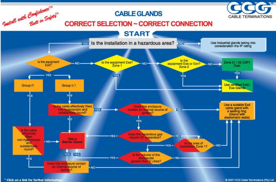
Select glands by using the flowchart for selection of cable gland for direct entry into a flameproof enclosure shown in the Figure 1.
If MICC cable is use must be fit with a suitable flameproof cable entry device. (i.e. Ex d MMIC gland)
The flowchart applies if thermoplastic, thermosetting or elastomeric cable is use. The cable must be compact, circular and effectively filled, with extruded bedding. Any filler must be non-hygroscopic.
DOWNLOAD: GLAND FLOW CHART SELECTION
According to IEC60079-14:2013. (In UK see BS EN 60079-14:2014 and National Annexe)
Also permit is the use of MICC cable with an Ex d MICC gland, or stopper box, sealing chamber, etc. with sealing around the individual cable cores, detailed in the equipment documentation.
In the UK, the selection process from the 2013 edition has been queried as not having any experimental basis, and for that reason a National Annexe to BS EN 60079-14:2014 recommends continue use of the flowchart from earlier editions.
To cover the requirements of both 2007 and 2013 editions of the IEC standard, it would be necessary to fit barrier glands on all cables that are less than 3m in length, and use the flowchart to select the appropriate gland for cables that are 3m or longer.
If a flameproof enclosure contains I.S. associated apparatus, all glands entering the enclosure, including those on the IS output cable, must be Ex d types according to the about producers.
Prior to 2007, the only requirements for glands for Ex e equipment meet the relevant IP rating and impact tests, and uncertified glands could be used.
This gland may be used with cables susceptible to ‘cold flow’, to avoid indentations in the cable insulation due to the force exerted by the compression seals of gland types. The cable gland selection table have represents part of the data available for many type of cable glands.
These glands are dual certified (comply with IECEx ITA 12.0014X; Standard: IEC 60079-0, IEC 60079-1, IEC 60079-7, IEC 60079-15, IEC 60079-31 & IEC 60529)
DOWNLOAD: CABLE GLAND SELECTION CHART
A barrier gland includes an epoxy resin compound which consolidates the cable cores and provides a pressure tight seal. In the event of an explosion in the Ex d enclosure, the seal prevents flammable gas or combustion products being forced through the spaces between the cable core to be released in the safe area or in other Ex equipment (possibly containing a flammable atmosphere).
The compound filled barrier seal in this cable gland prevents the effects of an internal explosion from reaching the cable. Generally, barrier glands are required for direct entry enclosures where the connecting cables are not circular, compact/filled, or where an enclosure is located in a IIC area and contains a source of ignition, or where an enclosure located in a Zone 1, IIA or IIB area has an internal volume greater than 2 liters, and contains a source of ignition.
These glands are dual certified (comply with IECEx ITA 12.0014X; Standard: IEC 60079-0, IEC 60079-1, IEC 60079-7, IEC 60079-15, IEC 60079-31 & IEC 60529)
References: Copyright © CCG Cable Terminations Pty Ltd